June 2013
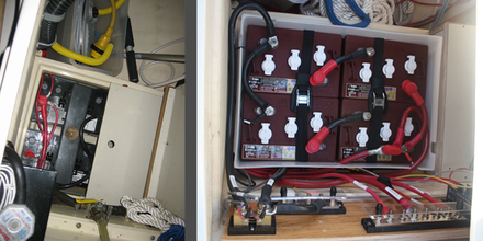
Before and After
Battery Bank Replacement – April-June
2013.
I had two main goals in revamping our electrical system. First, was to add more battery capacity – the more the better. Second, I wanted to make it as simple and user friendly as possible. This was a project that was 4 years in the making. I started by hiring a marine electrician. Bob, from Marine Electric Systems in Annapolis, MD, drove down and spent half a day on the boat looking at the existing setup and talking through what I wanted out of the system. I moved to California before I could hire Bob to do the work, but I relied heavily on his plan combined with A LOT more research.
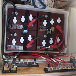
The first step was to determine the type of batteries to install. Initially, I was going to install AGMs due to their amp capacity and low maintenance. However, after doing more research it seems that AGMs may not be the best answer while full time cruising (read here). According to Lifeline, AGMs need to be regularly topped back up to 100% to stay healthy, which is hard to do when living full time on the boat. They are also expensive and do not have as many life cycles as wet cells. On the other hand, many cruisers have depended on golf cart 6 volt wet cell batteries because they are very affordable and common around the world. I originally wanted 600+ amps, but could not find the room for that many batteries. The current setup had the house batteries connected together but physically separated by about 10 feet, and I wanted the house batteries to be located all in the same spot. I went round and round trying to find the best place for the batteries and finally settled for the original factory placement within the cockpit locker. However, that spot was built for only two group 27 batteries (1 start and 1 house). After carefully measuring, I found that I could just fit four golf cart batteries if I cut a couple inches of fiberglass from the top lip of the battery compartment. When connected in series-parallel they provide a 12 volt, 450 amp bank.
Additionally, wet cells have the added advantage (or disadvantage) of having to check the water levels/specific gravity regularly. As much as I don’t need another regular maintenance task, I think this is a benefit because by regularly checking each cell’s specific gravity, I should be able to spot a dying battery cell before it takes out the entire bank. In theory then, if I found a dying cell I could disconnect two of the batteries still leaving me with a 100 usable amp bank until replacements could be found. While AGMs are “maintenance free” you have no idea if an individual cell has failed until the whole battery/bank fails, which would not be a welcome surprise in while on passage.
The downside was that I had to place the starting battery in a separate location. That became an easier decision as the previous owner had added a couple of batteries in a compartment under the chart table seat. Not an ideal location, but everything on a boat is a compromise and this is one of them. I kept the original start battery – an AGM start/deep cycle battery with a 100 amp capacity and 650 CCA for starting. Using the combo battery gives me a small (50 amp) emergency battery bank if the house bank dies unexpectedly. I reasoned that the start battery could be an AGM due to the relatively small energy demands and will most likely be kept fully charged in between starts, which AGMs like.
The next step was to make room for the new batteries, which seemed straight forward but, as usual...with boats nothing is easy. In order to have the room that I needed, I had to get rid of the installed hot water heater and modify the platform it sat on. Of course the hot water heater was connected to the engine fresh water cooling system. Since I had to drain the system, it was also a good time to clean out the heat exchanger and change out some of the old cracked engine hoses, change out the mixing elbow and replace the raw water impeller.
Weeks later, I was ready to cut fiberglass. I measured multiple times, took a swig of beer to calm the nerves, and then cut the port side of the battery box, effectively increasing the length by two inches. Fortunately, the width was OK and I didn’t have to cut too much. Due to the slope of the hull within this area, the batteries had to be raised up 3 inches to provide a flat area for the entire bank. This was done by creating a grid of cedar 2x4s that the batteries could rest upon. I also had to resize the small platform that the water heater previously sat on.
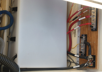
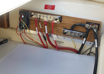
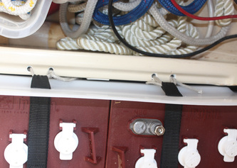
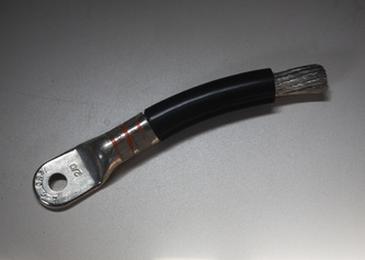
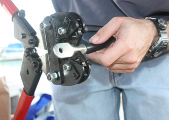
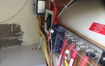
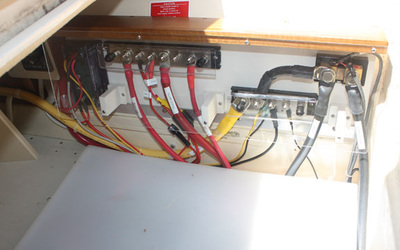
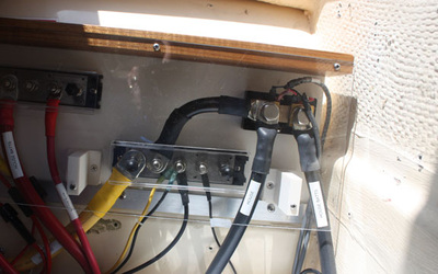
Next, I installed a battery box I found online and the four 6V Trojan T-105 batteries, and then began wiring the whole thing. I used kayak webbing tie downs bought at REI to hold all of the batteries in place since they are strong and stay tight once cinched down – I despise the cheap little plastic buckle tie downs that come with battery boxes. Wiring was fairly straight-forward once I finally decided on the placement of the bus bars and the wire routing. These decisions, however, were not easy and I labored over it for weeks until I was happy with the results.
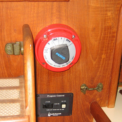
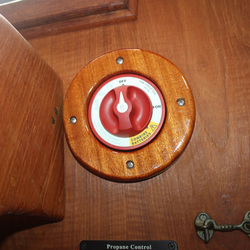
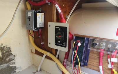
Lastly, I changed out the “1–2–Both–Off” battery switch to a Blue Seas “On-Off-Emergency” switch. With the old switch I ended up never using the start battery and always using the house batteries for everything because I didn’t like (or remember) to switch back to house after starting the battery. So, I ended up using the start battery as an emergency battery only. Also, Marya could never remember which one to select and we went through a Laurel and Hardy routine every time she messed with the switch. Now, with the new switch I have only to turn it on and the house batteries are connected to the main circuit breaker panel and the start battery is connected to the starter. If the start battery were to fail I can switch to “emergency” and the house batteries will now start the engine. Likewise, if the house batteries failed the emergency position will allow the start battery to power the house loads. Simple.
With this setup the solar panels, alternator and 110v battery charger are all connected to the house batteries for charging and set to charge wet cell batteries. The starter battery is charged through a Balmar Duo Charge which is connected directly to both battery banks. When the Duo Charge senses a charging current to the house batteries it sends a charge to the start battery set for AGMs, allowing me to have dissimilar battery types between banks.
For battery monitoring I chose to add a Xantrex Link Lite monitor, even though the existing Blue Sky IPN-ProRemote monitors the batteries. I had purchased the Link Lite awhile back as the primary monitor, before I had chosen to go with the Blue Sky system. I briefly thought of selling the Link Lite but then realized that the ProRemote would only monitor one bank (not the start battery). Besides, I like the Link Lite easy to read display and additional features. Besides, you can never have too much redundancy (helicopter thing).
The end result is a simple battery system to use (just turn it on or off), battery bank redundancy for emergencies, hands off charging, and easy and effective monitoring…at least in theory. So far, however, it seems to be working as advertised.
UPDATE: May 2014
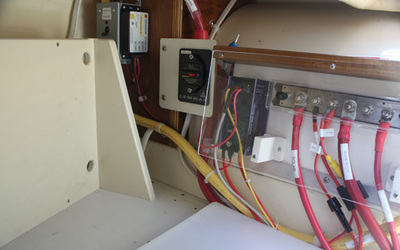
I finally made the final board for the electrical busses. I cut ¾” Starboard using the original plywood one as a template. Then I made a top out of teak and screwed on a 1/8” acrylic face plate to keep stuff from coming into contact with the wire connections and causing a short, or worse. It’s not water proof, but it should keep any errant drips off of the connections as well.
I installed a 50 amp ProCharge Ultra battery charger in place of the old 20 amp charger. The ProCharge also has the benefit of being able to take a wide range of voltage and hertz inputs, so that it can be used outside of the US.
I finally installed a Balmar serpentine belt and pulley system on the engine to take the load of the bigger alternator as well. I am still using the original (to me) Balmar 80 amp alternator and have yet to install the new 140 amp alternator. After about 20 hours of motoring (during the HA HA), however, I noticed that the serpentine belt jumped a groove on the water pump pulley. Using a straight edge, I determined that the water pump pulley was over an 1/8” off (set back to far) from the other two pulleys. I used a piece from the original pulley (basically a big washer with 4 holes in it), and used it to shim the pulley forward and nearly flush with the other pulleys. I’m not sure if the Balmar pulley is not machined correctly, or I have one made for a different motor. So far, after 40+ hours it seems to be working well with the shim I added. More later…
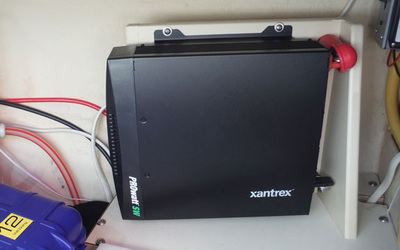
Lastly, I installed a 2000 watt Xantrex inverter where the hot water heater used to be, under the port seat. To simplify the setup, the inverter is wired directly to the batteries with 2/0 wire but is not wired into the AC system. The on/off button is located on the inverter and has two 110 standard 3 prong outlets. I can plug an extension cord directly into the inverter to run power tools, chargers, etc. Or I can plug my shore power adapter into it which allows me to plug my big yellow shore power cord into it. That way, the boat AC panel is energized and I can run everything on the panel, including my watermaker. Of course, installation was not straight forward due to the lack of space. I had to build a vertical bracket out of starboard in order to mount the inverter on its side, vertically. I fused it right at the battery terminal as I did with the battery bus and windless.

