Oct 2013
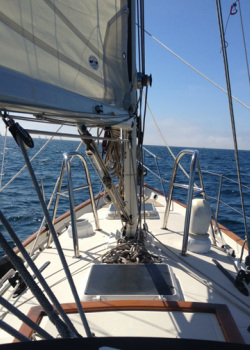
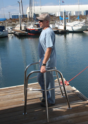
First test sail - already love them!
Mast Pulpits (aka: Granny Bars) – Oct.
2013.
This was my first major welding project and I chose to do it first because it is (or I thought at the time) to be pretty straightforward. I began by calling Thumper at PSC to see if I could order a new set. Turns out I can – for $2000. Ouch. Knowing that I had many more stainless projects that I wanted to do, it started to make financial sense to build my own, even if I had to buy a welder and other various metal working tools. But afterwards I could do other projects for essentially the cost of materials only. After looking at the cost of a radar arch (around $5000 for a basic arch), I knew this would make sense financially in the long run.
I decided to use 316L stainless vice 304 stainless. Type 304 stainless is much more common, cheaper and easier to find locally. Most of the metal work you see on boats at the marina is 304 stainless. However, 316L is more resistant to corrosion and used on most high end yachts, so I decided to spend the extra money and do it right.
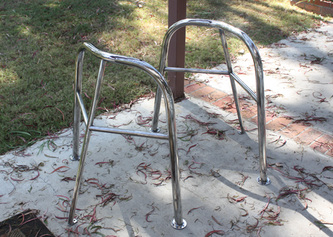
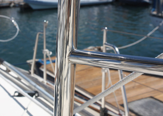
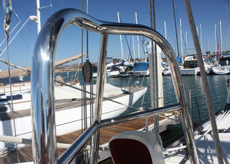
To begin with I started poring over every picture I could find of other people’s mast pulpits. They seem to come in every flavor with no two designs looking exactly alike. So, I started with the basic older PSC style (I believe the new design is different than the old large diameter single bar design). But instead of having essentially a two-legged design I decided on three legs. I liked the looks of the beefy 1 ½ inch main bar of the older design, but decided to add a 1 inch diameter third leg. Once OK’d with the Admiral, I began making a mock up.
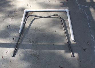
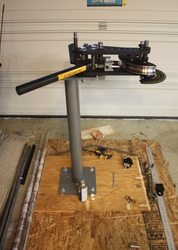
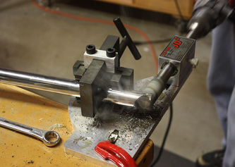
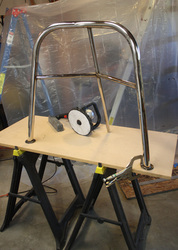
The first mock up consisted of three lengths of 1 ¼ inch PVC pipe and two 90 degree elbows. We took it to the boat, placed it roughly where we wanted it and cut the legs to the correct height and the horizontal piece to the correct length. Then I made another mock up using cheap 1 inch mild steel pipe. I marked out the configuration on the floor of my garage and figured out the bend angles. Then, bent the bar with a heavy duty manual tube bender and went back to the boat and checked it again. I then bent the two main pieces for both sides in 316L stainless. I also decided that I wanted the horizontal bar to curve outward which would create a small pocket to wedge your butt against, and it would give a little extra room to work at the mast. After playing with the placement I canted the bars out from the mast a bit, giving a bit more room to work and I also thought it looked better that way. Lastly, as part of the design progression, I added two horizontal bars that I could use as a step or a spot to tie halyards. (This actually worked out great as we can now step on it to clip the halyard on and tie the sail cover around the mast much easier.)
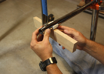
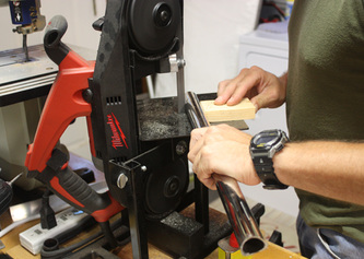
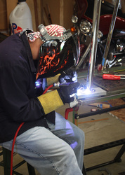
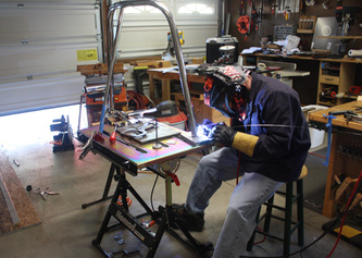
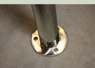
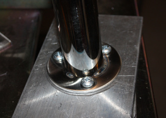
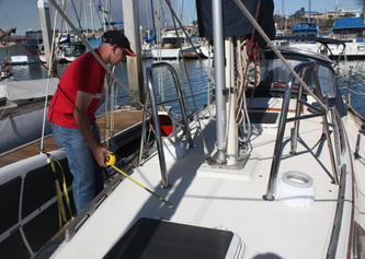
The trick to welding stainless, I found, is a nice tight fit up of the parts. To obtain those tight fits I had to make many trips back and forth to the boat to make sure it was measured and cut perfectly (one day I made 4 trips back and forth). The first step was to get the main (big) tube legs cut for the correct height and angle to the deck. The length was easy – pick a height (just under butt height) and cut it, but I had to take the compound angles into account. The legs are not 90 degrees to the deck, but rather each leg is bent to about 80 degrees. I carefully laid the tubes on the floor, measured the angle with an angle finder (each leg was slightly different), and then transferred that angle to the saw blade on my cut-off saw. This was repeated for each of the four legs. When I was finished, the tubes were cut perfectly for the fore and aft angles to the deck. Then I needed to measure the angle for the port to starboard angle (or outward lean) of the deck. I took the bent tubes to the boat, placed them carefully, measuring about a dozen times, and then used some line tied to the mast to hold the tubes in place at the proper angle. Since the tubes were cut square cross ways, the tubes made contact with the deck on the outboard side, leaving a small gap on the inboard side. I used a stack of playing cards to come up to the exact height of the gap, then carefully scribed a line all the way around the tube using the stack of cards as a gauge. Once done, I used a 4-inch grinder to grind down to the line and bingo, I had a perfect angle both fore and aft and laterally. I tacked on the base plates and it was then time for the 1 inch tubes.
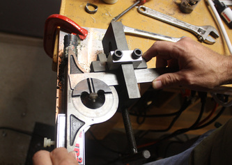
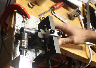
For the 1 inch leg support I started by setting up the main bars back on the boat and tying them up again at the proper angle, which would give me the length I needed for the leg. First, I cut the leg a couple of inches long, and placed the foot of the leg on the deck, laying the top portion against the main tube. Using the deck of cards trick I scribed the angle and went back home to cut the angles. Then I went back to the boat, and with the bottom angle set I marked the top of the tube right where it met the bottom of the main tube. I drove back home and notched the two leg tubes. A tube notcher is nothing more than a jig that holds the stainless pipe and drill angle as you drill a notch with a bi-metal hole saw. Using a 1 ½ inch hole saw, I cut a notch in the 1 inch pipe, which then fit perfectly flush with the 1 ½ inch main tube. Back to the boat again. This would have been much faster and easier if I could cut and weld at the marina, but nothing is ever easy. Everything fit perfectly so I scribed a mark on the big tube where I would weld the leg and also took multiple measurements to determine where the foot would sit on the deck in relationship to the main tube legs. Once at home I setup the leg angle again and tacked it to the main tube.
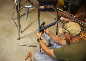
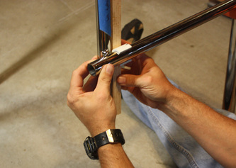
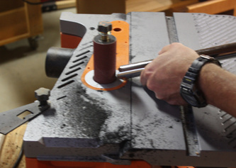
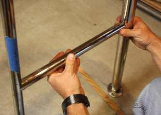
The horizontal tubes created an interesting problem because the angles where the tubes meet the main tube and the support leg are different – both are compound angles and each end is different. First I cut the horizontal tubes a couple of inches long. Then I marked where they would be placed with some blue painters tape. The tape allowed me to measure the angle I needed. Starting with the outboard ends first I measured the angle, marked the top of the tube for reference (in relation to the vertical tube) – adjusted the hole saw, cut, repeat 3 times. Then I switched out the hole saw to the smaller diameter 1 inch saw for the support leg side. I used a spring clamp to hold the bar in place on the outboard tube and then using a measuring jig that I made, marked the first support tube angle and the length. Then measured for the second support tube angle and transferred that angle to the hole saw jig, cut and repeated that 3 times. Once done I cleaned up the edges with the grinder and oscillating spindle sander and tacked everything in place. It took me a couple of hours to weld them both up and then it was off to polishing.
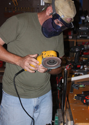
Polishing sucks and takes a lot of time. I started with a sanding flap disk (120 grit) on a 4 inch grinder to blend out all the scratches in the tubes. Then I switched the flap disk to a scotch type pad (extra fine) on the grinder to remove the scratches left behind from the flap disk. Then I went to a 4” felt polishing pad for the grinder with black polishing compound to remove the smaller scratches left by the scotch pad. Then on to a hard sisal wheel on an 8 inch grinder using black polishing compound followed by a softer sisal wheel with black compound. For tight spots I used a Dremel and black compound. After hours with the black compound, I switched to a clean sisal wheel and buffed the stainless to a high polish with green compound made for stainless steel. In the end, I spent more time polishing than I did fabricating and welding. The high price of stainless aside, I now see why stainless work costs so much.
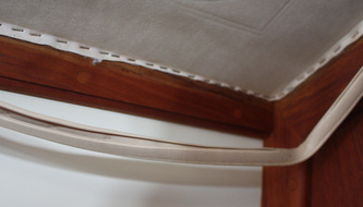
Finally, we were able to install it on the boat. First we had to remove part of the headliner which is a huge pain and time consuming. PSC used a zillion tiny staples to hold the headliner in place, and it took a lot of time and swearing to get them all out. Luckily, when I had installed the LED interior lights I had used socket terminals on the wire connections which made it really easy to unscrew and unplug them to get them out of the way.
Once I had access to the underside of the deck it was time to drill. After measuring about 6 times, walking around and looking at it from multiple angles, measuring down below to make sure we wouldn’t drill into a bulkhead; I marked and drilled all of the holes with a ¼” brad point drill, being careful to run the drill in reverse until the bit cut through the gel coat. If you try to run the drill normally it will chunk out big pieces of the gel coat as the drill bites too aggressively into the fiberglass. Once you get through the initial 1/16” to 1/8” then put the drill in forward and drill all the way through. Marya held the headliner away underneath to keep the drill from going through and also a shop vac to try and get most of the dust as the bit goes through.
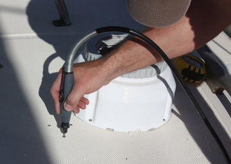
Once done, I used a Dremel with a little router type bit to hog out the plywood inside the hole. I’ve heard of using a bent nail, but the Dremel does a nice clean job, and a bent nail would be tough in a ¼ inch hole. Then I taped the top and bottom of the hole and filled it back in with epoxy to seal the wood from water ingress should a leak develop. I let it dry for a week (working the weekends) and then re-drilled the holes with the ¼” bit.
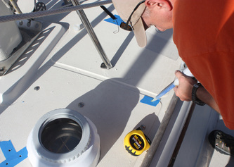
Since it is impossible (for me) to drill perfectly straight holes through the deck I knew the backing plates needed to be marked after the deck was drilled and not just transfer the hole pattern from the pulpit bases. I put some blue tape on one side of the backing plates, had Marya hold them up tight to the deck from the inside while I used the drill to lightly push down onto the plate, making small dimples in the tape. Once they were all marked, I punched a small dimple into the metal with an old tap (harder than an awl and won’t dull) and drilled them out with a 5/16” bit.
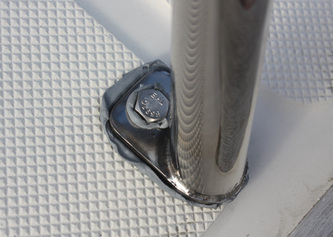
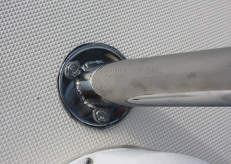
I then carefully applied butyl tape to each bolt and covered the bottom of each base plate and bolted it down. I did not use any sealant on the backing plates or bolts on the underside of the deck, because if water leaks past the deck sealant you want to know about it so that you can fix it. If you seal it from the bottom as well, then you risk the chance of the water making its way into the plywood or balsa core – not good.
Lastly, it was time to bolt everything down with stainless bolts. After learning the hard way (multiple times, I embarrassingly admit) I was careful to put some anti-seize on the bolts before threading on the nuts. If you do not, you risk the likely chance of the stainless bolt and nut galling together. It doesn’t take much pressure to completely fuse the two together and destroy it, and the only recourse is to cut the nut off the bolt. I tightened in stages to allow the butyl tape to squeeze out, and afterwards tore off the excess or used a plastic razor blade (I’ve only been able to find these online) to cleanly cut it without scoring the gel-coat. Finished.
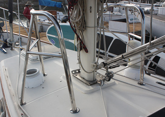
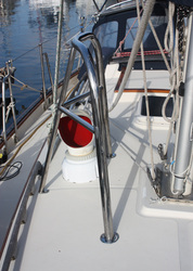
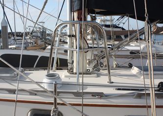
I am really happy how these turned out. I wanted something that looked professionally made, functional, yet compliment the lines of the boat. To my eyes, I think I accomplished that.

