July 2013
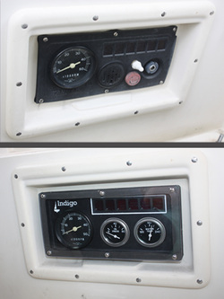
Before and After
Engine Panel Replacement with new oil pressure and engine temperature gauges – July
2013.
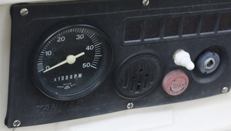
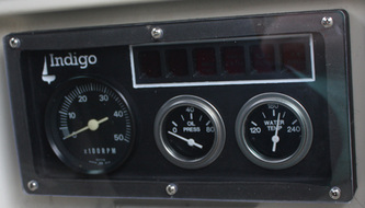
My engine has a “B” type engine panel with idiot lights only, and I wanted oil pressure and water temp gauges. As a pilot I am constantly scanning my gauges looking for potential problems before they become big catastrophic problems. So, this was a good time to add temperature and oil pressure senders. But, I had to figure out where to mount the gauges.
For a while now I had been trying to figure out what to do with the engine panel. I didn’t like the current location in the cockpit foot well due to its vulnerability to boarding seas. If the foot well were to fill with water, the electrical panel could be fried and the engine would be taken out of commission. I played with the idea of getting a Yanmar “C” panel that includes the oil and temp gauges, and installing a watertight opening porthole over it ($600 from New Found Metals). I also looked at relocating the entire panel either higher in the cockpit or moving it inside the cabin. Moving it higher only lessons the chances of water submersion but doesn’t completely alleviate it and moving it inside creates other problems. First, where do you put the panel? There is no room above the engine compartment for a panel so it would have to be moved above the quarter berth beside the hatchway, which would require extending the wire harness to get that high. Second, you would not be able to see the gauges unless you went below to check on them, which would not happen frequently, defeating the purpose of gauges in the first place. Lastly, the “C” panel cost around $1000 dollars, just to add two $40 gauges. Ridiculous.
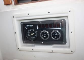
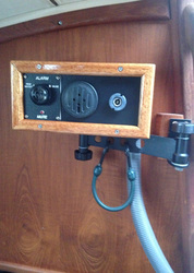
So, after flip flopping back and forth for a while, I finally decided on a different plan. I would design and build a new panel that would be waterproof and keep it in its current position in the foot well. This would allow me to see the gauges and not worry about boarding waves, and I wouldn’t have to cut more big holes in the boat. However, it would require a permanent, non-opening, waterproof cover (made of Lexan), requiring me to move the key and warning horn inside the cabin. Most panel covers protect against spray but not submersion because you need to allow for an opening in the cover for the key. Moving the key switch inside the cabin would allow me to install a permanent watertight cover. Since I was moving the key switch, I would also move the warning horn so that it could be heard better (a sealed cover would most likely mute the horn). A photo below shows that I moved the key/horn into a wood case attached to the swing-out arm at the companionway which used to hold the radar. This required splicing and lengthening some of the wires, but not the entire bundle. I may not leave this here but it works well for now.
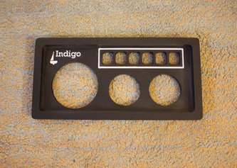
To design engine panel, I sketched it out on paper, arranging my newly purchased gauges, and then took it to the computer. Using Aspire software I created a drawing and program to run on my Dad’s 3D CNC router. He produced a test run in unfinished wood and mailed it to me so that I could verify dimensions. That test run was highly beneficial because I ended up having to make one of the gauge holes bigger and I also decided to make the entire thing a little deeper.
For the final product I used black King Starboard which cuts really well with woodworking tools, including the CNC router. The panel itself turned out perfect. But starboard is not really designed for the surface to be finished. Starboard comes with a dimpled surface that looks sharp, but also hides small imperfections. After routing the surface down you can easily see the router path and tool marks. I initially tried sanding it, but scratches were readily apparent even with 320 grit paper. I tried hand sanding with 1000 grit automotive paper but it too showed tiny scratches. I ended up using a Fein Multimaster and 400 grit “soft” sandpaper. The Multimaster’s rapid vibration seemed to sand the surface without leaving many scratches, which I then buffed out with a Black and Decker Mouse sander and a buffing pad. It still doesn’t leave a flawless surface, but I think it came out pretty well. I used some Rust-Oleum white paint to detail the name, logo, and highlights. I initially tried Testers model paint, but it is too watery and did not stick to the Starboard. The Rust-Oleum doesn’t stick well either, but it is much thicker and allowed me to build up multiple coats. Since the font, logo and border is recessed and protected from direct contact, it should hold up OK.
I faced the panel with 3/16 inch clear Lexan and used some rubber gasket material purchased from McMaster-Carr, which will hopefully waterproof the whole thing. The gauges, sending units, Starboard, wires, and Lexan cost a couple of hundred dollars – much cheaper than buying new panels, and I didn’t have to compromise on water integrity or placement visibility.

